Beginner’s Guide to Pin Header Connectors 2015
What is Pin Header Connectors?
Pin header is a type of electrical connector, this connector are widely used in electronic or instrumentation of PCB (Print Circuit Board) function as bridge between two PCBs which were blocked, and used to take current or signal transmission.
When pin headers connector mated with header connectors (Female header called “header connector”) called Board to board connector(click to view more on WIKI) connection. Mated with cable connectors called Wire to board connection such when it function as recipients for jumper wire.
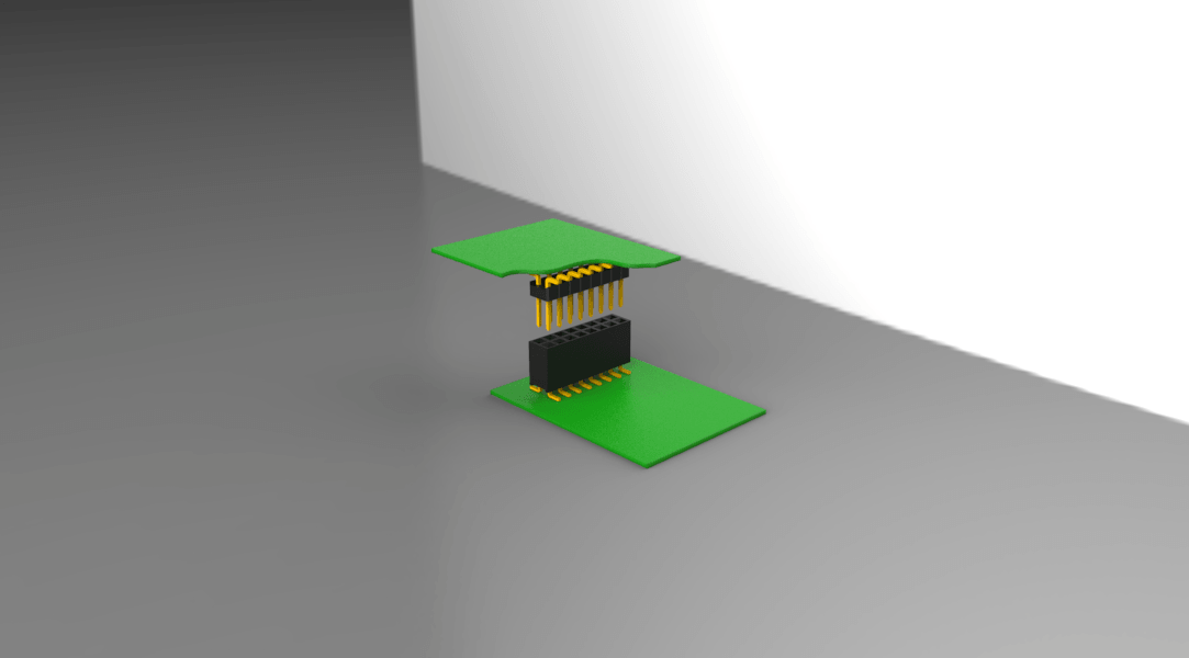
Board to board connection
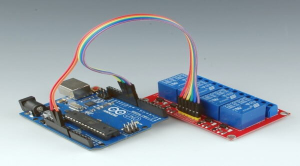
Wire to board connection
Basic Introduction
1. By pitch(spacing):
Pitch refers to the distance or space between two pins in electronic community, more details check Wikipedia
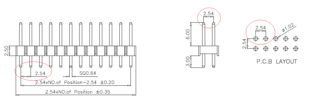
- -2.54mm (.100”) inch pitch pin header connectors ( typically and widly used)
- -2.00mm (.079”) inch pitch pin header connectors ( widly used)
- -1.27mm (.050”) inch pitch pin header connectors ( used as well)
- -1.00mm (.039”) inch pitch pin header connectors ( for small device)
- -0.80mm (.032”) inch pitch pin header connectors ( for smaller device)
2. Number of rows:
- Single row pin header connectors
- Dual rows pin header connectors
- Triple rows pin header connectors
- Quad rows pin header connectors ( Max )
Number of rows depend on the PCB board’s design, and considering the Current. Single and Dual row are normally than others.
3. Number of pins:
The pins for per row generally is depend on the pitch. for standard pitch such as 2.54mm and 2.0mm has 2-40 pins, and smaller pitch like 1.27mm and 1.0mm has 2-50 pins per row. Sometimes there are special module can make over 40 pins or 50 pins header, it’s according to the requirement from customers and need to consider the performance before production.
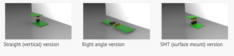
4. Version:
- Straight (Dip or Vertical) pin header connector
- Right-angle ( 90 degree) pin header connector
- SMT (surface mount, SMD) pin header connector
5. Materials:
Contact materials:
- Brass
- Phosphor Bronze
- other: Beryllium or Copper Alloy
-Plating materials:
- Gold (Au) plated (surface flashing)
- Tin-plated (main plating materials)
- Nickel(Ni) plated (underplating)
-Insulator materials (UL94V-0)
- PBT (Polybutylene Terephthalate)
- Nylon6T Nylon66/46 PA6T/4T/9T so on.
- LCP (Liquid Crystal Polymer)
6. Package:
- Box or Poly-bag: generally for the goods not easy to broken.
- Tube:it’s good choice for right-angle and SMT version.
- Tape&Reel: for Auto machine to assembly.
7. Production Process:
- Choose Brass or Phosphor Bronze to produce the pin (metal contact pin)
- Plating the pin according to customer’s requirement.
- Machining the insulator part by mould.
- Use the equipment to insert (assemble) the pins to insulator.